详情介绍
淘宝店链接:https://item.taobao.com/item.htm?ft=t&id=582482852004

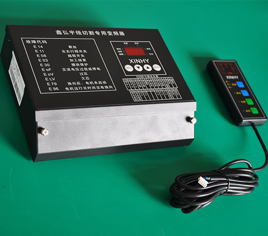

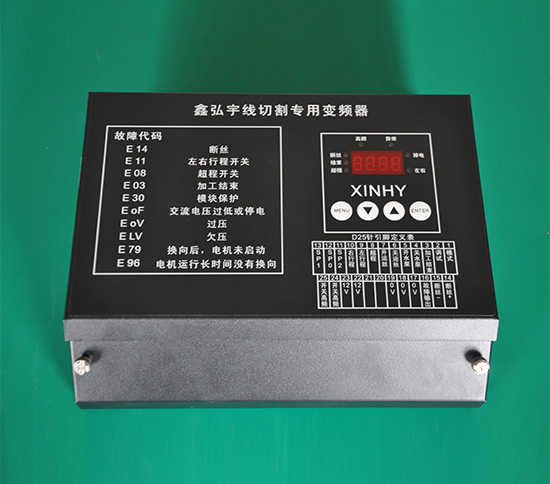
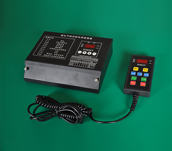
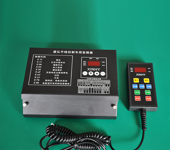
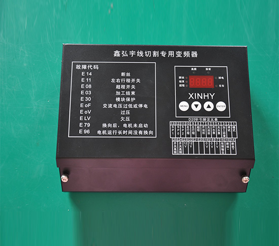
XINHY-MK Frequency Converter Parameter Adjustment Table for Wire Cutting
menu | project | Adjustment range | Function Description | Factory default | Remarks | Currently used value |
0P | 0P0 | d00-d80 | 0 speed frequency | d 15 | unit:HZ | |
0P1 | d00-d80 | 1 speed frequency | d 20 | unit:HZ | ||
0P2 | d00-d80 | 2 speed frequency | d 25 | unit:HZ | ||
0P3 | d00-d80 | 3 speed frequency | d 30 | unit:HZ | ||
0P4 | d00-d80 | 4 speed frequency | d 35 | unit:HZ | ||
0P5 | d00-d80 | 5 speed frequency | d 40 | unit:HZ | ||
0P6 | d00-d80 | 6 speed frequency | d 45 | unit:HZ | ||
0P7 | d00-d80 | 7 speed frequency | d 50 | unit:HZ | ||
1P | 1P0 | d00-d50 | acceleration time | d 08 | 0.0-9.9S | |
1P1 | d00-d30 | deceleration time | d 06 | 0.0-9.9S | ||
1P2 | d00-d06 | Torque boost at low frequencies | d 02 | |||
1P3 | d00-d60 | Automatic power saving percentage | d 20 | |||
1P4 | d00-d49 | Overvoltage regulation | d 30 | unit:V | ||
2P | 2P0 | d00-d99 | Turn on high frequency delay | d 10 | 0.0-9.9S | |
2P1 | d00-d20 | Maximum time allowed to power down | d 01 | |||
2P2 | d00-d02 | Stop mode after processing | d 00 | =00, stop immediately; =01, stop on the right; =02, stop on the left; | After receiving the processing end signal, the pump always stops immediately | |
2P3 | d00-d15 | Starting frequency of starting, reversing and braking | d 05 | unit:HZ | ||
2P4 | d00-d00 | Enter the "debug" state mode selection | d 00 | =00, the second pin of D25 pin and the debugging on the hand control box are both effective (if there is a hand control box); =01, only D25 pin 2 is for debugging; =02, only the debugging on the hand control box is effective; =03, debugging and water pump linkage, debugging when the water pump is not turned on. | ||
2P5 | d00-d15 | Broken wire detection delay time adjustment | d 00 | 0.0-1.5S | ||
3P | 3P0 | d00-d01 | ------------------ | ------ | --------------- | Not used yet |
3P1 | d00-d01 | ------------------ | ------ | --------------- | Not used yet | |
3P2 | d00-d01 | ------------------ | ------ | --------------- | Not used yet | |
3P3 | d00-d01 | High frequency polarity adjustment | d 01 | |||
3P4 | d00-d01 | ------------------ | ------ | --------------- | Not used yet | |
3P5 | d22-d38 | Motor connection selection | d 22 | =22: The motor is 220V connection (delta connection) =38: The motor is 380V connection (star connection is also called Y connection) | ||
3P6 | d00-d01 | -------- | ----- | --------- | Not used yet | |
3P7 | d00-d01 | ----------------- | ----- | ---------------- | Not used yet | |
4P | 4P00 | d 00-d 01 | Data write protection | d 01 | =00, the parameters can be modified; =01, it is forbidden to modify the parameters. | |
4P01 | d 00-d 01 | Restore factory value | d 00 | When =00, it is the normal state; when =01, press the "confirm key" to restore the factory value. |
When 2P4 is 0, if there is a hand control box, both the "debug" on the D25 pin and the "debug" on the hand control box will work, depending on the signal of the last action. This point is mainly designed for the compatibility of models with manual control box and without manual control box.
When 2P4 is 1, only the "debugging" on pin D25 works. When the second pin of D25 pin is connected to 0V, it is in the debugging state, and the signals of "processing end" and "broken wire detection" are not detected, but disconnected from 0V When the "processing end" and "broken wire" signals are valid, the machine will immediately decelerate and brake to stop.
When 2P4 is 2, if there is a hand control box, only the debugging on the hand control box will work.
When 2P4 is 3, "processing end" and "broken wire detection" are automatically adapted and linked with the water pump. The water pump is not turned on, and the signals of "processing end" and "broken wire detection" are not detected, which is equivalent to the original "debugging" state; after the water pump is turned on, when the "processing end" or "broken wire detection" signal changes from "normally open" to "normal" When “closed” or “changed from normally closed to normally open”, it will stop immediately, the corresponding abnormal code flashes, and it can be directly turned on again. Simply put: when the "processing end" and "broken wire detection" signals change, it will stop immediately, and it can still be turned on again. So these two signals can be connected to normally open and normally closed.
When the pump is not turned on, the overtime protection (the abnormality caused by the long time no commutation after the high frequency is turned on when the motor is running) does not work. Startup protection (abnormalities caused by not turning on high frequency for a long time after the motor reverses) does not work.
Increase the delay time adjustment of broken wire detection (2P5). Adjust this value appropriately to prevent frequent shutdowns when the molybdenum wire shakes. This value cannot be too large, otherwise the detection time will be longer when the wire is broken, which will cause a delay in the shutdown.
Exception code display:
Display on the host:
The MK type inverter adds the abnormal code display function. When there is an abnormality such as overtravel, end of processing, broken wire, simultaneous operation of left and right commutation, wrong polarity adjustment, power failure, etc., the corresponding abnormal code "E XX" will be displayed. . When the abnormality is removed, the abnormal code will be displayed flashing. When any one of the keys for turning off the water pump, turning on the water pump, turning off the wire, or turning on the wire is pressed, the abnormal code display can be cleared and the operation of the button itself can be executed. If the abnormality persists, the abnormal code will be stable It shows that operations such as boiling water pump and Kaiyun wire will not work.
Digital tube display content | meaning | The function of this pin in D25 |
E 08 | Overtravel | Pin 8 of D25 pin is "overtravel" |
E 03 | End of processing | The third pin of D25 needle is "processing end" |
E 14 | Broken wire | The 14th and 15th pins of D25 needle are "broken wire" |
E 11 | The left and right commutation act simultaneously or the polarity is adjusted wrong | The 9th and 10th pins of D25 pin are "left and right reversal" |
E 79 | After commutation, the motor does not start | ---- |
E 96 | No commutation for a long time during motor operation | ---- |
E 30 | Internal module protection | ---- |
E oF | AC voltage is too low or power failure | ---- |
E oV | Overpressure | |
E LV | Undervoltage |
Display on the hand control box:
The abnormal code of MK type inverter on the hand control box is correspondingly displayed with LED lights. When there is: overtravel, end of processing, broken wire, simultaneous movement of left and right reversing, abnormal power failure, the corresponding LED light will light up. When there is an abnormality all the time, the light is always on, and it cannot be turned on. When the abnormality is cancelled, the light will flicker. At this time, press the wire or water pump button, the flashing light will immediately go out and the water pump or wire will be turned on immediately.
The MK type inverter can be connected with external switches for wire movement, water pump buttons, or external speed control switches.
The MK type inverter uses DIP switches to adjust the polarity of overtravel, end of processing and left and right travel switches. This is a function that all previous models do not have. In addition, the polarity of these three items cannot be adjusted in 3PXX. Water pump (wire transport) Button mode selection is also controlled by dial switch. See the figure below for details.
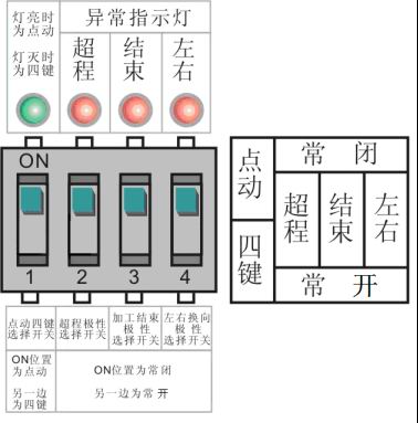
This type of inverter adds "broken wire", "overtravel", "processing end" and "left-right commutation" abnormal indicators. When an abnormality occurs, its corresponding abnormal indicator light is on. When there is an abnormality, the light is always on , It can’t be turned on at this time; when the abnormality is removed, the light will flash. When any one of the keys for turning off the pump, turning on the water pump, turning off the wire, and turning on the wire is pressed, the abnormal light is off, and the operation of the button itself is executed.
The parameters of the MK inverter can be adjusted either on the host or by the manual control box.
Key operation:
After the power is turned on, if there is no abnormality in the external port, the current segment speed and target frequency value will flash. For example, when the current working is at the 0th speed and the target frequency is set to 15HZ, the flashing display is 0.15. After starting the wire, the current speed and actual running frequency value are displayed stably. This MK type has 8 speeds. When the external ports SP2, SP1, and SP0 are all suspended, it will automatically switch to the speed control of the hand control box. When the speed is controlled by the hand control box, there will be one of the high speed, medium speed, and low speed lights on the hand control box. When the low-speed light is on, the host displays 0.15, when the medium-speed light is on, the host displays 4.35, and when the high-speed light is on, it displays 7.50. The order of the lights corresponding to the speed control key is: low→medium→high→medium→low, and cycle in turn.
When any one of the external ports SP2, SP1, SP0 is connected to 0V, it will automatically switch to the external port speed control, the high speed, medium speed, and low speed lights on the hand control box will all go out, at this time the "speed control" button of the hand control box It doesn't work. When the external ports SP2, SP1, SP0 and 0V are disconnected again, it will automatically become high-speed.
When the debugging key is pressed and the debugging light is off, the "processing end" and "broken wire detection" signals are detected. When the debugging light is on, the inspection of these two signals is ignored, that is, when the "processing end" and "broken wire" signals appear, The wire tube will not stop. Generally, the debugging state is used when winding the wire (the debugging light is on).
In the factory default state, the data in 4P0 = 01, all parameters can only be viewed but cannot be modified. Press the "parameter 1" "parameter +" key to modify the parameter, the number will not change.
If you want to modify the parameters, please modify the data in 4P0 to 00 first. After debugging, please modify the data in 4P0 to 01 to prevent the parameters from being modified at will.
Press the menu key to switch between 0P, 1P, 2P, 3P, 4P, 7.50. "Parameter -" "Parameter +" keys can add or subtract items or add or subtract parameters (the item is the value after P, the parameter is the value after d). For example: when 0P0 is displayed, press "parameter +", 0P1 will be displayed; press "confirm" key, the parameter d 20 in 0P1 will be displayed, press "parameter +", d 21 will be displayed, press "OK" ”Key to save and execute the adjusted parameters, and return to 0P1. If you do not press the “Enter” key, directly press the “Menu” key to return to 0P1, and the modified parameters will not be saved.
When the yarn spool motor stops, the adjusted parameters will be saved immediately after pressing the "confirm" key. When the wire spool motor is running, the parameters can also be adjusted. It will be executed immediately after pressing the "confirm" key, but it will not be saved immediately. The wire spool motor needs to be stopped once to save. If the wire tube is not stopped once and the power is cut off directly, the parameters may not be saved!
Press the enter key on the 7.50 interface to switch between the external port status, voltage display (U XX), and current display (A XX). The external port status displays the external wiring status (see "External port status display" below for specific usage); the voltage is displayed as the DC voltage across the large capacitor. Since the inverter host has only 3 digital tubes, the displayed voltage is multiplied by 10 The actual voltage across the capacitor, such as U 26 is displayed, the actual voltage across the large capacitor of the inverter is 260V, if the hand control box is equipped, the digital tube display voltage of the hand control box is the actual large capacitor voltage, and there is no need to multiply it by a certain multiple ; The current is displayed as the current flowing through the motor, and the current of the main unit is displayed in tenths of precision. If the main unit displays A 0.8, the current flowing through the motor is 0.8A. If the hand control box is equipped, the digital tube of the hand control box displays 100 Quantile accuracy. Voltage display and current display are unique functions of this inverter.
●"1P0 acceleration time" is the time required for the inverter to accelerate from "2P3 start frequency" to 50HZ. The smaller the value, the faster the speed change, and the larger the value, the slower the speed change. The unit of "1P0 acceleration time" is 0.1 seconds, for example: d=12 in 1P0 means that the acceleration time is 1.2 seconds.
●"1P1 deceleration time" is the time required for the inverter to decelerate from 50HZ to "2P3 braking start frequency". The smaller the value, the faster the speed change, and the larger the value, the slower the speed change. The unit of "1P1 deceleration time" is 0.1 seconds, for example: d=12 in 1P01 means that the deceleration time is 1.2 seconds.
● "1P2 low frequency torque boost" is used to adjust the motor torque when "auto power saving function is not started", the larger the value, the greater the low frequency torque boost. =0, no increase, =1, 10%,=2, 20%,=3, 25%,=4, 30%,=5, 35%,=6, 40%. As shown below
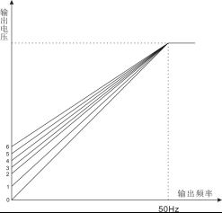
When d=00, no torque increase is performed.
When d=01, the output voltage is increased to 10% of the maximum output voltage at low frequency.
When d=02, the output voltage at low frequency is increased to 20% of the maximum output voltage.
When d=03, the output voltage at low frequency is increased to 25% of the maximum output voltage.
When d=04, the output voltage at low frequency is increased to 30% of the maximum output voltage.
When d=05, the output voltage at low frequency is increased to 35% of the maximum output voltage.
When d=06, the output voltage is increased to 40% of the maximum output voltage at low frequency.
If the value is too large, the motor current may be too large when starting, and the motor will overheat for a long time. This value should be adjusted gradually from small to large. The value should be as small as possible when the required starting torque is obtained. In general, sufficient commutation speed can be obtained when d=02.
●"1P4 overvoltage adjustment" is to adjust the threshold of the inverter's overvoltage protection (that is, the critical value for displaying the fault code E 0U). The adjustment range is 0-49V. This value plus 400V is the overvoltage protection threshold. If adjusted to 30V, when the voltage across the large capacitor is detected to be greater than 430V, the inverter will display E oV, and the motor will decelerate and brake to stop. When it detects that the maximum voltage is 450V, the inverter immediately stops output, and the motor is in a free-running stop state without braking.
● It is recommended to use "delta connection (220V)" for wire drum motors as shown in the left figure below:
● If only 3 wires are drawn from the inside of the wire drum motor, it is likely to be "star connection (380V)". At this time, in order to obtain a faster commutation speed, the "1P02 low frequency torque boost" can be appropriately increased, d=03 Or d=04. Generally, many motors that have been repaired are connected in this way.
● When the wire tube is "triangular connection (220V)", please adjust 3P5 to d=22
● When the wire tube is "star connection (380V)", please adjust 3P5 to d=38
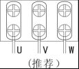
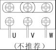
"Delta connection (220V)" "Star connection (380V)"
3P05 is adjusted to d=22 (factory default value) 3P05 is adjusted to d=38
● Please adjust the parameters in 3P5 according to the actual connection method of the motor. Incorrect adjustment may cause the motor to overheat, or damage the motor in severe cases.
●"2P1 maximum allowable power-down time" is adjusted according to the stability of the grid voltage. When the AC input voltage is greater than 150V, it is considered to be powered on, and when the voltage is less than 100V, it is considered to be powered down. The unit is 0.1 seconds, for example: d=02 in 2P1 means that the longest time for power failure is 0.2 seconds.
●"2P3 start, commutation, brake start frequency" set the output frequency when the inverter starts, the frequency when the wire drum switches the direction and the start frequency of the brake when stopping. In order to increase the speed when starting, reversing, and stopping and braking, this value can be adjusted to be greater than 0, but when it is too large, it will cause commutation shock and slower commutation speed. Generally, this value is set to 05, which means starting When the inverter starts to output from 5HZ, it gradually accelerates to the set frequency. When commutation, it decelerates from the set frequency to 5HZ and quickly switches the steering, re-accelerates to the set frequency, and starts to output DC when the set frequency decelerates to 5HZ when stopping. Brake pulse.
● Display when braking: dc After braking, the current speed and frequency value will be displayed.
●"1P3 automatic power saving percentage" determines the amplitude of the inverter output voltage automatically falling after the high frequency is turned on, for example: when d=10, the voltage will be automatically reduced by 10% after the high frequency is turned on. The larger the value, the smaller the heat generation of the motor. If it is too large, the running speed of the motor will become slower and slower or even stop. Please adjust according to the resistance of the wire tube, generally this value is not more than 40. This function is mainly designed for "middle wire walking", which can make the motor run at low speed for a long time without heating.
External port status display:
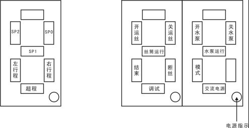
In 7.50 (running or stop) state, press the OK key to enter the "port status display" interface. The strokes of the three digital tubes in the figure above represent the status of each external port. When the external port is connected to 0V, the stroke of the digital tube is on, and it is off when it is disconnected. This function is mainly used to check whether the external wiring is correct and whether the signal is sent to the inverter.
When the confirmation key is pressed several times, it returns to 7.50 (run or stop) state. In the "port status display" interface, you can also press the "menu" key to enter the parameter adjustment interface for parameter adjustment. When exiting, the "port status display" interface is still displayed.
Restore factory value:
First change the value of "4P0" to d= 00, allowing to modify the parameters, and then change the value of "4P1" to d=01, after pressing confirm, all parameters will be restored to the factory values. The operation of restoring the factory value can only be performed when the wire spool motor is stopped. During operation, under the d=00 interface in "4P1", the "increase" and "decrease" keys do not work, and d=00 cannot be adjusted to 01.
D25 pin pin definition table:
13 | 12 | 11 | 10 | 9 | 8 | 7 | 6 | 5 | 4 | 3 | 2 | 1 | |||||||||||||
SP1 | SP0 | SP2 | Right stroke | Left stroke | Overtravel | Turn on wire | Turn off wire | Turn on water pump
| Turn off water pump | End of processing | Debug | mode | |||||||||||||
25 | 24 | 23 | 22 | 21 | 20 | 19 | 18 | 17 | 16 | 15 | 14 | ||||||||||||||
open turn off high frequency | open turn off high frequency | 12 V | 12 V | 0 V | 0 V | 0 V | Fault output | Broken wire detection- | Broken wire detection+ | ||||||||||||||||
Connection method for broken wire detection:
The 14th and 15th pins of D25 needle are broken wire detection, among which the 14th pin is "broken wire +" and the 15th pin is "broken wire -". During installation, the wiring method of these two signals is as follows:
① The 14th pin (broken wire +) of the D25 pin of the inverter must be connected to a separate conductive block on the machine tool
② The 15th pin (broken wire-) of the D25 pin of the inverter must be connected to the negative (sampling-/high-frequency-) conductive block on the machine tool
Can’t connect reversely, if the connection is reversed, the broken wire detection circuit of the inverter may be burnt out at the moment of wire breakage。
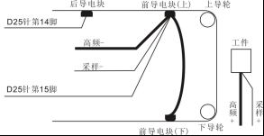
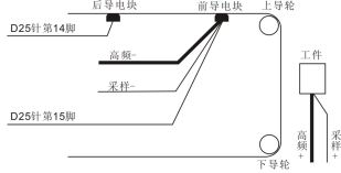
Connection method for three conductive blocks Connection method for two conductive blocks
Solution when encountering problems:
1. After opening the filament tube, it turned very fast at first, the more it turned, the slower it turned, and then it stopped. The HFP light in the upper left corner of the digital tube is still on, and the HFP light is off after shutting down.
Solution: MK type inverter has added the "automatic power saving" function. The inverter will automatically reduce the voltage output to the wire drum motor after turning on the high frequency. If the "automatic power saving percentage" is adjusted too large, the wire drum resistance will be relatively high. Large, this will happen. The "automatic power saving percentage" should be adjusted down, and the "low frequency torque boost" should be adjusted up.
If the resistance of the wire spool is too large, it should be repaired first, or the "automatic power saving percentage" should be adjusted to 0, and the "automatic power saving" function should not be used.
2. For the newly installed inverter with manual control box and DIP switch, if the wire and water pump cannot be started when the power is turned on, and there is no fault code display, the digital tube will display "Segment Speed" and "Frequency Value". The solution is to check the status of the "four keys" and "jog" on the DIP switch of the inverter. If there is no connection between the D25 pin on pin ④ water off, ⑤ boiling water, ⑥ off wire, and ⑦ on wire, set it to point If the inverter with a manual control box is connected to the water-boiling, water-off, wire-on and wire-off button controls, the button control on the DIP switch must be consistent with the external button control.
- 没有了
- 没有了
